How to Control an LED Using a Button with Arduino Mega
Welcome to this beginner-friendly tutorial by Madras Academy, where you'll learn how to control an LED using a push button with Arduino Mega. This fundamental project is perfect for students and electronics enthusiasts starting their Arduino journey!
In this tutorial, you will:
- Wire a push button and LED to Arduino Mega
- Write basic Arduino code for digital input/output
- Understand how buttons trigger LED actions
- Learn about pull-up resistors (software implementation)
This project lays the foundation for more complex interactions and is a great first step in physical computing.
👉 Use the tabs below to navigate through the project:
- Project Info & Demo – See the final result and project overview.
- Wiring & Code – Get the circuit diagram and complete Arduino code.
- Notebook & Help – Access project documentation and troubleshooting tips.
Let's build your first interactive Arduino project!
📌 Project Information
- Title: Control LED with Button using Arduino Mega
- Difficulty: Beginner
- Build Time: 10-15 minutes
- Skills Gained: Digital I/O, button input handling, basic circuit design
🎬 Demo Video
Watch the project in action below:
🧰 Components List
This simple project requires just a few basic components to create your first interactive circuit:
Essential components:
- Arduino Mega: The microcontroller board that will process the button input
- Push Button: Momentary switch to control the LED
- LED: Any color you prefer
- 220 ohm Resistor: Current limiter for the LED
- 10K ohm Resistor: Pull-down resistor for the button (optional with internal pull-up)
- Breadboard & Jumper Wires: For easy circuit assembly
| Component | Quantity | Description |
|---|---|---|
| Arduino Mega | 1 | Main controller board |
| Push Button | 1 | Momentary tactile switch |
| LED | 1 | Any color |
| 220 ohm Resistor | 1 | For LED current limiting |
| 10K ohm Resistor | 1 | Pull-down resistor (optional) |
| Breadboard | 1 | For building the circuit |
| Jumper Wires | 5-7 | For connections |
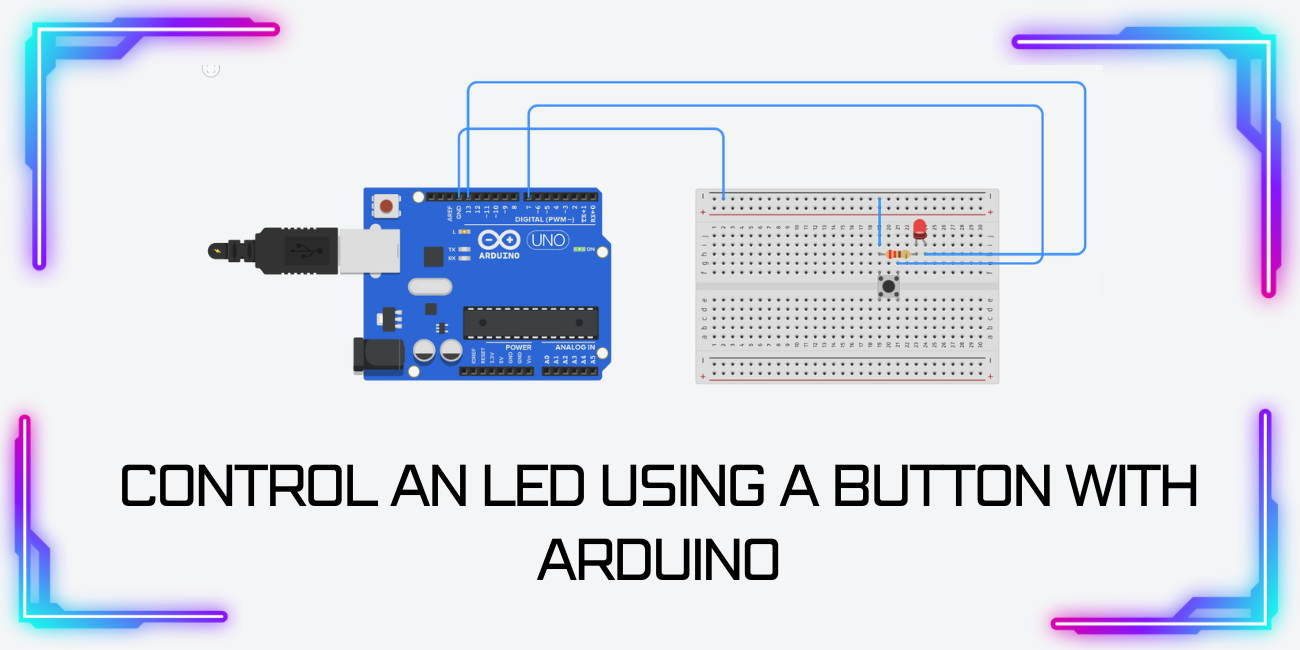
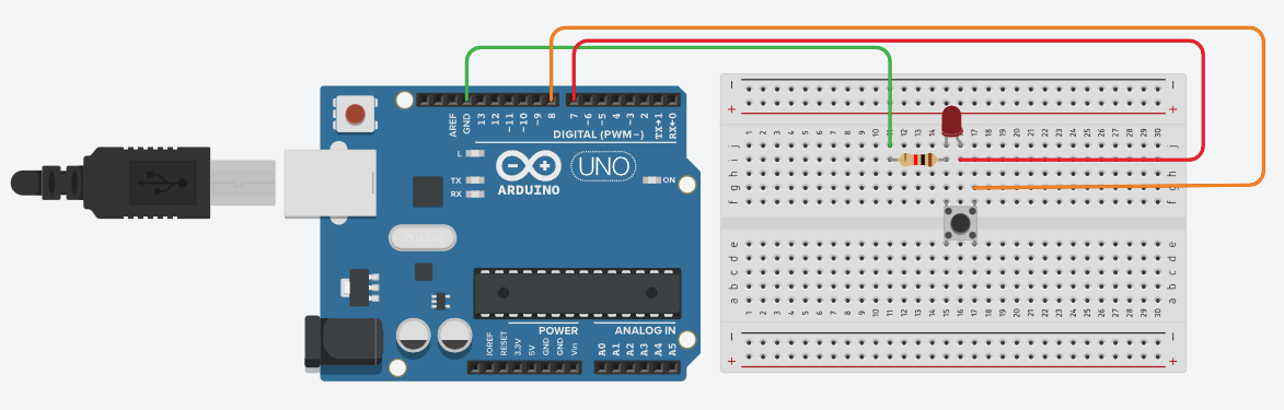
🔌 Circuit Diagram
💻 Arduino Code Example
const int buttonPin = 2;  // Push button connected to digital pin 2
const int ledPin = 13;    // LED connected to digital pin 13

int buttonState = 0;      // Variable to store button status

void setup() {
pinMode(ledPin, OUTPUT);      // Set LED pin as output
pinMode(buttonPin, INPUT_PULLUP); // Set button pin as input with internal pull-up
}

void loop() {
buttonState = digitalRead(buttonPin); // Read button state

if (buttonState == LOW) {  // Button is pressed (LOW because of pull-up)
digitalWrite(ledPin, HIGH); // Turn LED ON
} else {
digitalWrite(ledPin, LOW);  // Turn LED OFF
}
}
Note: We're using the Arduino's internal pull-up resistor, so the button connects between the input pin and GND.
📘 Project Notebook Template
- Project Title:
- Date:
- My Objective:
- Materials I Used:
- Circuit Diagram:
- My Custom Pattern Idea:
- What I Learned:
- Challenges I Solved:
🛠 Troubleshooting Tips
- ✅ Check LED polarity (long leg to +, short to GND)
- ✅ Verify button connections (should connect between input pin and GND)
- ✅ If using external resistor, ensure proper wiring (10K for pull-down)
- ✅ Test with Serial.println(buttonState) to debug button readings
- ✅ Try different digital pins if one isn't working
🎓 Learn More
Enhance your skills with our Arduino Beginners Course: https://www.madrasacademy.com/arduino-adventures-beginners-course
- Duration: 3 Days
- Total Lectures: 15
- Capacity: Max 50
- Difficulty Level: Advanced
- Medium of Instruction: English
Project Cost
₹1,500 ₹3,000